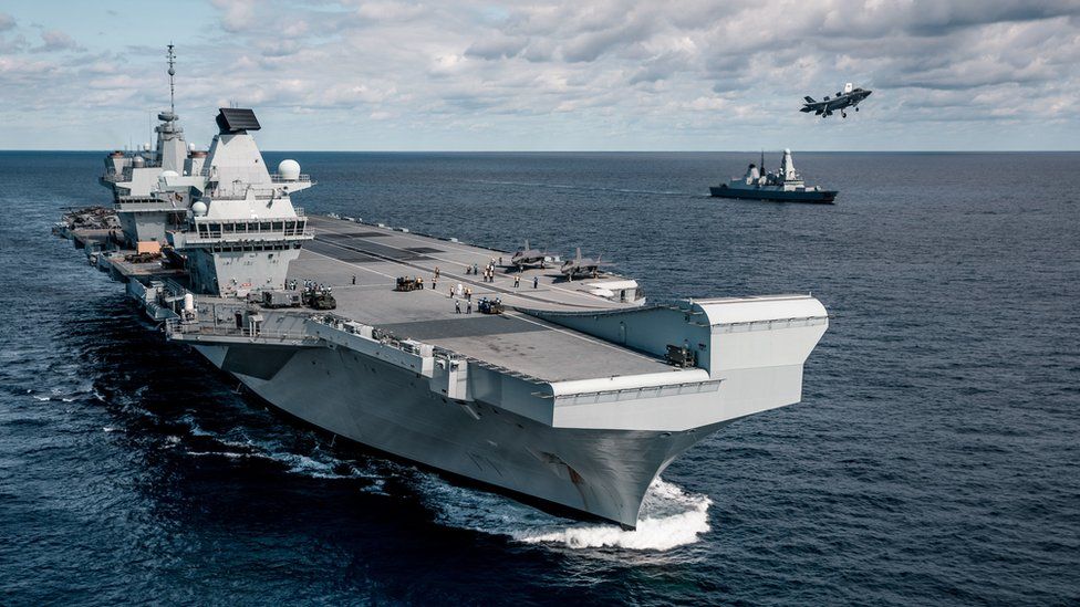
Undocking the Aircraft Carrier HMS Queen Elizabeth
Presented by Alan Dodkins and Adam Clarkson at the International Dry Dock Conference
Introduction
This presentation examines the undocking of the newly built HMS Queen Elizabeth. It explains the docking plan design philosophy, identifies flood-up and undocking risks, and outlines the processes developed to manage them.
The Challenge
The project required a coordinated construction strategy, major modifications to Rosyth Dockyard’s Dry Dock No. 1, a robust docking arrangement, and careful control of weight, stability, flood-up operations, and vessel extraction.
- Design work was completed at two sites, CAD modeling at four sites, and block construction at six shipyards.
- The dock entrance was widened, altar steps and the mid-caisson were removed, and 3 m-high dock blocks with a skidding arrangement were installed.
- A 1,000-tonne safe working load (SWL) Goliath gantry crane was constructed for the project.
- The finite element analysis (FEA)-based keel block design utilized 340 blocks arranged in five rows, with particular attention given to the suing point and after-end blocks.
- Crushable softwood caps were tested to reduce suing loads and improve load distribution.
- Support towers were installed beneath the stern overhang.
The Solution
The Aircraft Carrier Alliance, comprising BAE Systems Maritime, Babcock Marine, Thales UK, and the UK Ministry of Defense, combined their expertise to deliver one of the United Kingdom’s largest and most complex engineering projects.
Undocking Process
The team addressed several operational uncertainties, including:
- Watertight integrity across approximately 3,000 compartments.
- Incomplete outfitting and uncertain weight distribution.
- Predicted hull-girder hog curvature.
- Limited heel clearance.
- Heel and trim monitoring.
- Ballast transfer requirements.
- Vessel control during float-off and extraction.
- Tidal and weather constraints.
- Schedule pressures.
Control measures included floating fenders, observers stationed at forward, midship, port, and starboard draft marks, an additional aft draft marker, pilot viewing platforms, onboard inclinometer monitoring, and teams prepared to reposition ballast as required.
The dock was initially flooded to about 1 m below the float-off draft, after which the team reviewed inclinometer readings and made ballast adjustments as needed. Flooding then continued to float-off draft, and the vessel floated free with less than 0.1° of heel.
Results
Condition Capture
- Approximately 3,000 compartments were surveyed.
- An electronic equipment register was created, and 360-degree photographic records were captured.
- Stakeholders were engaged to establish and quantify the margin of error.
- Movable ballast requirements were specified, and water-ballast quantities were progressively refined using measured on-site flow rates.
- An initial water-ballast requirement of 3,400 tons was established and subsequently refined following condition-capture activities.
Float-Out Simulation
- Vessel extraction was simulated with harbor pilots.
- Movements were planned in two dimensions.
- Three-dimensional simulations were conducted with tug masters.
Conclusions
- Crushable softwood caps effectively reduced suing loads.
- Estimated weights, validated against individual block loads, were sufficiently accurate.
- Condition capture proved to be the most challenging task because incomplete outfitting made missing weight difficult to quantify.
- Movable deck ballast provided an effective means of correcting transverse center-of-gravity errors, although the inclinometer was less useful for assessing longitudinal balance.
- The vessel floated with nearly level trim, although a slight stern trim would have been preferable.
- Following extensive modeling and simulation, flood-up and undocking were completed successfully in favorable weather conditions.